

Metal welds of different metal compositions are a frequent joining method of two sections in the construction of nuclear power facilities. Here we report on our computer simulation of one of these “dissimilar” metal welds in a pressuriser safety relief line.
The weld has a complex manufacturing history, including for example transition layers to the intended weld, heat treatment, and machining, before attachment of an extension pipe. The results of the analyses have been used to help interpret the behaviour of the nozzle welds on the plant.
The weld has a complex manufacturing history, including for example transition layers to the intended weld, heat treatment, and machining, before attachment of an extension pipe. The results of the analyses have been used to help interpret the behaviour of the nozzle welds on the plant.
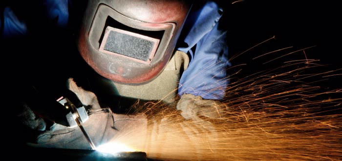 |
| Metal welds of different metal compositions are a frequent joining method of two sections in the construction of nuclear power facilities. |
Description of weld
Our finite-element computer simulation of a pressurising safety relief line for a dissimilar metal weld procedure has been performed in collaboration with British Energy (BE) - Electricité De France (EDF)1 . BE-EDF has contracted an external constructor to manufacture mock-ups of welds in one of their power stations, Figure 1, as part of a project to assess the risk of primary water stress corrosion cracking and to develop an appropriate mitigation strategy.
The simulation work was carried out partly to gain experience in this form of analysis prior to participation in an upcoming international Nuclear Regulatory Commission (NRC) round robin, and partly to address perceived deficiencies in existing simulations performed by other contractors. The weld has a complex manufacturing history: it comprises over 90 buttering passes to provide a transition layer from one material to the intended weld material; after application of the buttering layer intermediate heat treatment followed to relax stresses.
This treatment led to machining of the butter layer in order to provide a new welding surface. Using 46 transition layers, so-called“passes”, the main dissimilar metal weld could be applied, and finally the extension pipe could be attached via a standard metal weld of the same metal composition.
The large number of weld passes proved a challenge to model efficiently with many software tools being developed to augment the existing packages (Abaqus [1] and FEAT weld modelling tool [2]) used for this type of analysis. The results of the analyses have been used to help interpret the behaviour of the nozzle welds on the actual plant.
In order to perform this simulation with a degree of confidence a considerable amount of background work has been carried out in conjunction with BE-EDF and the European Network on Neutron Techniques (NeT). NeT has organised several round robins for simplified welding simulations and measurements whose sole purpose was to identify the key elements to accurate welding simulations and verify the results using advanced measurement techniques [3]. The key elements identified in successful welding simulations are:
- an accurate heat-source model utilising an appropriate heat-flux energy distribution; and
- detailed temperature-dependant material properties both thermal and mechanical
Simulation procedure and results
In the current work as much detail of the welding procedure as possible has been incorporated in the model. For simplicity, several sequential axi-symmetric (2-dimensional) models were developed. Each model was used in turn to provide the stress/strain field for the next step in the welding process which included surface machining to remove excess material.
In overview the nozzle/extension, Figure 2, undergoes several steps in its construction: 1) application of an Inconel 82/182 buttering layer to the SA508 ferritic steel nozzle, 2) machining of the transition layer, i.e. buttering layer to provide a good welding surface, and 3) 46 pass welds for attachment of the nozzle/buttering layer to the stainless steel 316L extension.
Traditionally, buttering layers and weld passes might be applied in a single lumped step in order to simplify computational effort with the assumption that this did not significantly affect the final results. In this work, all 93 passes of the buttering layer and 43 passes of the extension weld attachment were individually applied. At the end of each step, the results were mapped to a new model where the outer layers could be removed to simulate the machining of the weld surface.
As thermocouple records were taken during the mock-up construction each pass was allowed to cool until the “actual” interpass temperature had been achieved, at which point the current step was automatically terminated and the next pass commenced. This is a level of detail that is rarely possible and did provide a noticeable variation in the resulting residual stress field, Figure 3.
A full cyclic strain hardening law (tensile/ compressive) was applied for all three materials used in the construction of the dissimilar weld. Once again, this level of detail is rarely utilised in welding simulations primarily due to the lack of accurate test data and the necessary experience in applying the properties to a numerical material model.
A further level of material complexity was applied with the use of two-stage annealing for both strain relief then strain hardening. This final step was shown to have only a limited influence on the resulting residual stress field.
The lessons learnt will enable more accurate solutions for a wide range of welding situations with a better insight on what is important to consider and what can be omitted to accelerate the process in what is a very time consuming analysis.
With the knowledge and experience gained from the current study we have pushed the boundaries of accurate welding simulations for residual stress determination. Considering that welds are the most common joining method in high temperature plants the applications will be many and varied.
Further work will include combining our complimentary knowledge on creep/fatigue analysis and applying this to estimate the life exhaustion of the material resulting from the welding process alone.
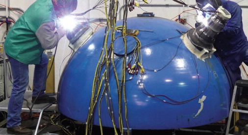 |
| Figure 1: Mock-up construction of nozzle and safe-end extension on pressure vessel end cap. Nozzles are constructed under identical welding conditions either side. |
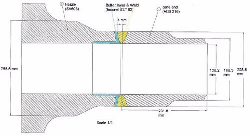 |
| Figure 2: Section view of dissimilar weld. Nozzle attached to pressure vessel end-cap. |
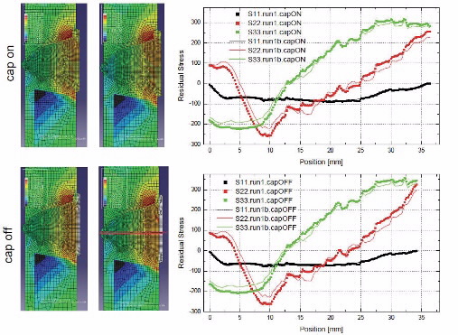 |
| Figure 3: Through thickness hoop stress profiles (left) with bead cap on (top) and removed (bottom). Implied interpass temperature control (left and dotted), accurate T/C interpass temperature control (right and solid line). Directions: S11-through wall; S22- transverse to weld path; S33-hoop. |
Authors
Ondrej Muransky1, Philip Bendeich1, Lyndon Edwards1 and Mike Smith2
1 ANSTO and 2British Energy- Electricite De France
References
- SIMULIA. AAQUS/Standard. Dassault Systems, 2009
- Smith RM. FEAT-WMT: Weld-Modelling Tool 1.0.9 User Guide. 2008.
- Smith MC, Smith AC. NeT bead-on-plate round robin: Comparison of residual stress predictions and measurements. International Journal of Pressure Vessels and Piping; 86 (1): (2009) 79-95.