

Reactor engineering seeks to improve the safety and increase the efficiency of nuclear reactors. Research conducted at ANSTO in this area recently looked at a technique called 'roll swaging' and its role in ensuring the integrity of fuel plates during nuclear operations.
 |
| Example of the fuel rods in the OPAL Research Reactor at ANSTO |
Plate-type nuclear fuel assemblies, such as those used in ANSTO’s OPAL research reactor, consist of a number of thin aluminium plates containing a uranium-aluminium mixture. Typically, the fuel plates are secured into a box-type fuel assembly using a technique termed ‘roll swaging’.
The strength of the roll swaged connections determines the integrity of the fuel assembly as a whole, therefore it is very important to have a non-destructive method to verify that the roll swaged connections are secure. Since the interaction between fuel assemblies and coolant flow during reactor operation can lead to flow-induced structural instabilities [1-3],it is crucial to be able to predict their dynamic characteristics and how these are affected by the strength of the roll swaged connections.
Previous research has investigated the instability of parallel plates due to fluid velocity, sometimes leading to plate collapse. The aim of the present work is to provide a computational and experimental justification for the model used in reference [7].
This will be the first step in achieving a qualitative test method for assessing the quality of plate-type nuclear fuel assemblies.
The results of this work will be used to model a whole fuel assembly made of multiple plates restrained by the roll swaging technique.
We performed experimental modal analysis on test swage specimens manufactured with different swaging parameters, resulting in varying swage strengths.
The boundary conditions of the swage joint as modelled by a finite element model (FEM) were determined by matching the experimental values of the first natural frequencies measured with the results obtained from the FEM.
It was shown that the swage contact between the thin plates and side plates can be modelled assuming a perfect clamp in all the degrees of freedom except the rotational around the axis parallel to the swage, where an equivalent torsional spring stiffness can be applied.
Construction of a swaged joint
In a typical fuel assembly, the plates are inserted into slots machined into the side walls of the fuel box. The clamping of the plates to the box is generally assured by a swage between adjacent plates.
The swage is obtained by forcing the sharp edge of a swaging wheel into the aluminium ridge between the slots, resulting in plastic deformation of the ridge to create the clamp as shown in Fig. 1 (see image library below). The nature of the clamp is a key element in predicting the vibrational behaviour of a fuel assembly.
A perfect clamp completely constrains all six degrees of freedom at the edges of the fuel plates.
In this present work it is shown that the swaging process results in a clamp that fixes all the degrees of freedom but the rotational around the axis parallel to the swage.
For small rotations, the effect of the swage joint is shown to be a torsion spring whose stiffness is related to the quality of the swage. A good swage leads to a very high stiffness that approaches the ideal case of a perfect clamp, while a poor swage results in a lower stiffness value tending to a simply supported case.
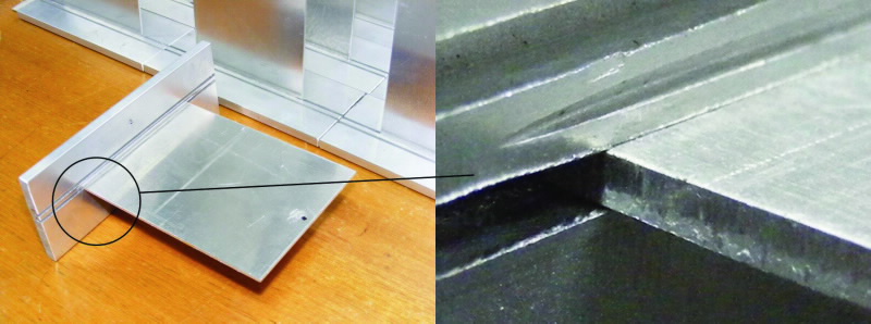 |
| Fig 1. A swaged specimen used for the modal analysis tests detailing the swaged connection (right image) |
Experimental aspect
The natural frequencies of the specimen plates were determined by clamping the bottom of the side plates in a vice and performing an impact hammer test to obtain the Frequency Response Function (FRF).
A laser fibrometer was used to measure the response, focussed close to the corner of the plate to maximise the visibility of all the modes. We found that different swaging parameters shifted the natural frequencies, with a dependence on the integrity of the swage connection.
Computational aspect
Using data obtained from the experiments, an FEM of the specimen was built connecting the plate to the support using 6 degree of freedom elements with adjustable torsional stiffness Ks.
The first five natural frequencies for a perfect clamp situation (Ks → ∞) are shown in Fig. 2, represented as their vibrational mode shapes.
Different stiffness values for the torsion spring, simulated the conditions between a perfect clamp (Ks → ∞) and a simple support (Ks = 0).
The first five natural frequencies were normalised with respect to the perfect clamp case and plotted against spring stiffness (Fig. 3). The first natural frequency is the most sensitive to variations in spring stiffness.
Sensitivity decreases approaching the ideal clamped case and with higher-order modes.
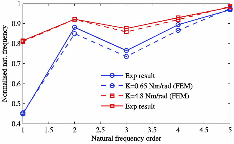
Arranging the data with respect to the natural frequency order, a characteristic stepwise variation between perfect clamp and simple support was observed (Fig. 4). The equivalent experimental results obtained by swaging at different distances from the plates, thus changing the strength of the swage, showed the same trend.
Matching theoretical and experimental data
Fig. 4 compares the first natural frequencies of two experimental results depicting a poor swage or loose connection and a good, but not perfect swage, with the FEM results obtained by updating the stiffness values of the torsion springs.
The characteristic stepwise variation can be seen at the second order. The maximum error between experiment and FEM for higher-order natural frequencies is around 3%.
The matching of experimental and theoretical results confirm the validity of the FA model, showing that we can assess the dynamic behaviour of a swaged connection by means of torsion springs with adjustable stiffness.
This is a first step to model the dynamic behaviour of thin plates secured by swage joints in nuclear fuel assemblies and opens a variety of issues to be studied in more depth.
A more sophisticated FEM updating process able to match the results of higher orders of natural frequencies will give an improved value for the equivalent torsion spring.
Further validation of the results can be achieved by finding the sensitivity of the natural frequencies to additional swaging parameters such as depth of cut (swaging force) and the profile of the swage wheel.
The results of this work will be used to model a whole fuel assembly made of multiple plates restrained by the technique of the roll swaging.
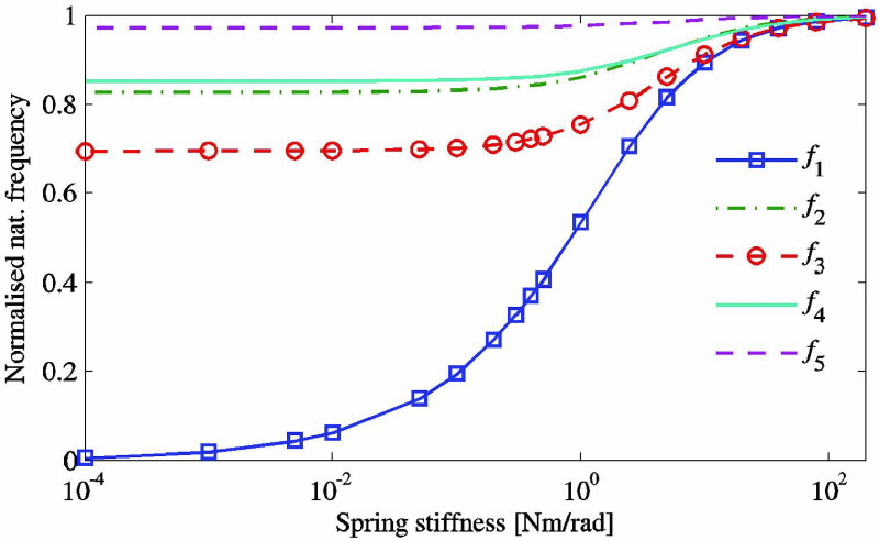 |
| Fig 3. Variation of the natural frequencies calculated using the FEM with the spring stiffness applied to the joint. |
|
| Fig 4. Matching the natural frequencies obtained by experiment with the computational natural frequencies by FEM updating. |
Authors
Mauro Caresta 1, David Wassink 2
1 University of New South Wales (UNSW) Sydney, 2 ANSTO
References
- Blevins, R. D. (1979). Flow-induced vibration in nuclear reactors: a review. Progress in Nuclear Energy, 4(1), 25-49.
- Païdoussis, M. (1980). Flow-induced vibrations in nuclear reactors and heat exchangers: practical experiences and state of knowledge. In E. E. Naudascher & D. Rockwell (Eds.), Practical Experiences with Flow-Induced Vibrations (volume 829-832, pp. 1-81). Berlin, Germany: Springer-Verlag.
- Ho, M., Hong, G., & Mack, A. N. F. (2004). Experimental investigation of flowinduced vibration in a parallel plate reactor fuel assembly. 15th Australasian Fluid Mechanics Conference, 13th – 17th December 2004. Sydney, Australia: The University of Sydney
- Miller, D. R. (1960). Critical flow velocities for collapse of reactor parallel-plate fuel assemblies. Journal of Engineering for Power-Transactions of the ASME, 82, 83-95.
- Pavone, S. J., & Scarton, H. A. (1983). Laminar flow induced deflections of stacked plates. Nuclear Engineering and Design, 74(1), 79-89.
- Davis, D. C., & Scarton, H. A. (1985). Flow-induced plastic collapse of stacked fuel plates. Nuclear Engineering and Design, 85(2), 193-200.
- Kim, G., & Davis, D. C. (1995). Hydrodynamic instabilities in flat-plate-type fuel assemblies. Nuclear Engineering and Design, 158(1), 1-17.
Published: 28/09/2011