

Science is coming to the aid of railway engineers in Australia to help them produce and maintain safer and longer lasting rail lines that could be used around the world through the use of neutron diffraction.
 |
| Bonded IRJs are safety-critical components that must satisfy requirements for structural integrity as well as the isolation function for both railway signalling and track condition monitoring systems. |
Insulated rail joints (IRJs) are an integral part of any rail track system, as they split a continuous rail track into electrically isolated sections for signalling and easy detection of rail track damage. Bonded IRJs are safety-critical components that must satisfy requirements for structural integrity as well as the isolation function for both railway signalling and track condition monitoring systems.
In heavy haul corridors in Australia and around the world, IRJs are periodically replaced due to accumulated damage in their railhead, often within 10-20% of the useful life of other rail components.
Their replacement is the single largest track maintenance cost in New South Wales, apart from track ballast work. Neutron diffraction can tell us what happens to material and residual stresses within used rails and trace down accumulation of damage caused by stresses throughout rail service history.
The study is helping railway engineers better understand how residual stress fields evolve in service and enable them to develop IRJs with longer service lives, as well as determine the most appropriate rail maintenance and replacement schedules for safe and economic operation.
Role of stress in rail damage
A number of serious incidents, including fatal derailments and train-on-train impacts, have been attributed to rail and rail-end failures resulting from rolling-contact fatigue. Most of the various mechanisms of rail failure are related to the interaction between defects and the residual stress field at and below the rail surface.
Residual stresses are generated in rails first as a result of the manufacturing processes, which include hot-rolling (shaping rails from a billet), rollerstraightening (final cold rolling through multiple rollers to achieve geometrical tolerance) and head-hardening (heat treatment to achieve high hardness).
In service, the running surfaces of rails are subjected to repeated rolling-contact loading through interaction with train wheels, and the rail itself is subject to a variety of complex stresses and strains.
Stresses are usually so high that they can cause plastic deformation around the contact surface and modify the stress field and material properties near the running line and internally in the railhead. Track fracture can result from one or more progressive defects, the propagation of which is also influenced by residual and contact stresses in the rail.
IRJs and their damage
The above mentioned effects change significantly in IRJs because they are somewhat different from continuous rail. Essentially IRJs comprise two rail ends and a narrow gap in the rail filled with insulator, and a support structure including bolted fishplates on both sides of the rails, which are electrically isolated from the track by a layer of glue and help add rigidity to the IRJ, as shown in Fig. 1. IRJs represent a different support structure to standard tracks as they endure an additional impact-forces distribution arising from the wheel-to-rail contact in special conditions of the rail gap and the rail ends.
For example, failure can occur when metal flows over the insulated rail gap (typically 6-8 mm width) breaks the electrically isolated section of track and results in malfunction of the track signalling system. This can happen well before any other defects, such as cracks or surface voids, start to develop.
Therefore, a significant amount of track maintenance work is dedicated to the inspection of rail ends. As a maintenance procedure the head of the rail may be ground periodically to restore the correct head profile, to remove surface cracks before they grow too big, or to move the wheel-rail contact position across the vicinity of the end-post in order to extend the life of the IRJs.
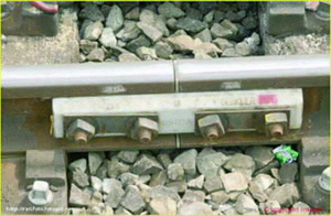 | 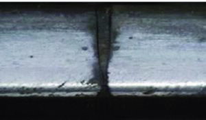 |
| Left: 4-bolt square ended IRJ: two rail sections are connected by means of bolted fishplates on both sides of the rail; an insulator, placed in the gap between two rail sections, forms a rail-post. Right: Metal flow in damaged end-post. |
In case of severe damage, when the rail is approaching an unsafe condition, rail sections containing IRJs are replaced. In heavy haul rail systems, IRJs’ periodical replacement due to accumulated damage in their railhead may be necessary after only 2-3 years of service or within 10% of the useful life of other rail components. Apart from track ballast work, IRJ replacement represents the most significant track maintenance expense in the rail network.
Researching IRJs
A research project was initiated by the Cooperative Research Centre for Rail Innovation to address this problem and supported by industrial partners (the Australian Track and Rail Corporation, Queensland Rail) and academic institutions (University of Wollongong, Queensland University of Technology, University of Central Queensland).
We use neutron diffraction to investigate the material stress accumulation at rail ends in the vicinity of the insulated gap in IRJs - this is the area of rail subjected to the most damage.
By selecting a series of samples with different service histories the investigation provided fundamental information about residual stresses accumulation, material properties evolution and how these might change during degradation of IRJs. The samples selected for this investigation are rail ends from squareended IRJs made from the same steel type (Australian standard A1085.1 60 kg grade) and manufacturer.
Rail ends from IRJs described as ‘partly damaged’ and ‘badly damaged’ will be compared with a rail end in the ‘not damaged’, as-manufactured, condition.
Neutron stress measurements
Neutron diffraction is particularly suited to the nondestructive mapping of complex internal stress fields within dense materials such as steel, because of the high penetration.
For neutrons the penetration depth in steel is 100 times greater than that of X-rays. There are a handful of known examples of use of neutron diffraction to investigate residual stresses in rail and most of the studies have been performed on rail slices because the railhead thickness of 70 mm is still too great even for neutrons.
Although stresses are partially eliminated by slicing, this approach allows stresses to be mapped much faster, more accurately and over larger areas.
In our study one transverse slice and one longitudinal slice was machined out of each rail sample. They were studied in residual stress experiment with gauge volume (probing volume) of 2 x 2 x 2 mm3, accuracy of ±30 MPa and using the iron (211) Bragg reflection.
Mapping the stress
(1) Drastic changes in residual stress state were found in the rail head of the selected samples, see Fig. 2. Compressive stress (shown as blue areas) immediately under the top surface, which is induced due to the service load from train movement, is counteracted by a wide zone of tension (red areas) that potentially can cause defect growth (Fig. 2a).
The rail material also undergoes transformation as shown in Fig. 2b changing from harder steel (shown in red) to softer (shown in blue). This happens differently across railhead and evolves noticeably with the service span.
(2) The distributions of stresses close to the end-posts are different from the bulk parts because of different loading conditions and this is demonstrated in Fig. 3a.
The material close to the IRJ rail end-post is more damaged then material in the continuous rail as shown in Fig. 3b by a differential stress map for the longitudinal component. Damage accumulation is mostly happening 5-10 mm beneath the surface and progresses with rail service (can be seen as enhancement of the features in Fig. 3b).
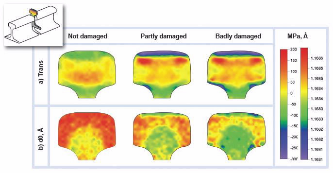 |
| Evolution of the residual stress and material lattice parameter in rails of different service history. The railhead is 70 mm across. a) In the stress maps, the red areas represent high tensile stress while the blue areas correspond to high compressive stress. b) In the lattice parameter maps, larger d-spacing are shown in red while small d-spacing values are blue. |
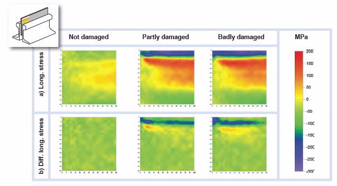 |
| a) Evolution of the residual stress longitudinal component in rails of different service history obtained on longitudinal slices (maps top left corner corresponds to the top corner of the end-post). Patch size is 60 x 60 mm2. b) Differential longitudinal stress component maps are obtained by subtracting stress values representing bulk material from the values representing material of IRJ. |
Projected outcomes
The stress distributions determined experimentally can be used to validate finite-element simulations carried out at Queensland University of Technology to assess progressive damage accumulation in material of IRJ through elastic-plastic deformation history and residual stress evolution. Our detailed stress maps will allow us to narrow the selection of the correct material mechanical models and damage mechanisms.
The combined experimental and modelling efforts will help railway engineers to better understand how residual stress fields evolve in service and enable them to develop IRJs with longer service lives, as well as to determine the most appropriate rail maintenance and replacement schedules for safe and economic operation.
Authors
David Wexler2, Chandrahas Rathod2, Huijun Li2, Manicka Dhanasekar3, Vladimir Luzin1
1ANSTO, 2University of Wollongong, 3Queensland University of Technology, CRC for Rail Innovation
Published: 30/10/2012